 |  |
|---|---|
 |
Quadcopter v3:
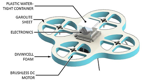
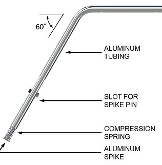
3. A final waterproof design was created but never fully deployed. This design centered on a Divinycell foam frame providing buoyancy to the quadricopter as well as providing protection to the propellers and motors from side impacts. The electronics were consolidated onto a 4 level platform that could be easily attached to the foam frame using several bolts, and a watertight seal was made using a rubber foam gasket. The electronics were protected on the top as well using a plastic container mounted to the frame in the same way as the electronics insert. The landing gear for this design was simplified from design 2; rather than relying on a pivoting leg, aluminum tubes were used as the leg, and a spring was placed between the leg and foot of the landing gear.
Quadcopter
Project: Quadcopter for Environmental Monitoring
(Master’s Thesis)
Timeline: 1 year (Jan. 2013 – Jan. 2014)
# of participants: 1 Person
Project Goals:
-
Stable, straight flight at low altitudes
-
20+ minutes of flight time
-
Remote Controlled (autonomy desired)
-
Downward facing camera for high-speed image collection
-
Low cost and Portable
Quadcopter v1:
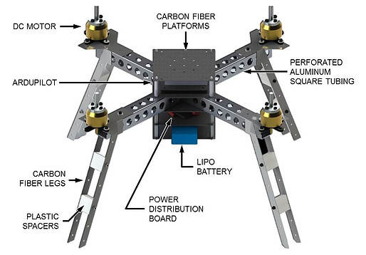
1. The first frame was rather simplistic, and was made of perforated aluminum tubing with an arm span of approximately 15 inches. All of the electronics were supported on several carbon fiber sheet platforms and rigid landing gear was used. This design, although relatively lightweight when compared to the subsequent designs, was not very stable in flight and did not have sufficient space for additional components.
Quadcopter v2:
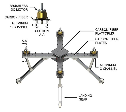
2. The second design centered on a frame made of aluminum c-channels and carbon fiber. This was done in such a way that the frame arms were hollow allowing for wiring and small electronics to be placed within the frame preventing damage from the propellers or impacts. The frame’s arm span was increased to 24 inches and because of this the stability was noticeably increased. The landing gear for this design reduced rigid impacts upon landing by modifying the legs to absorb some of the impact. The landing gear consisted of pivoting aluminum u-channels with 3D printed spring-loaded pistons that absorb energy during landing to prevent damage to the arms. At the same time this energy is used to prevent the quad from flipping when landing askew, as the stored energy creates a moment opposing the tendency of the vehicle upon landing.
This design was used for several outdoor tests in both laboratory settings and in the natural environment; however, there were more risks associated with the flight because the project goal involved having the quadcopter fly over water systems. Therefore, in the event of a crash, many of the electronic components could be damaged when contacting water.
Sample Output Velocity Map:
A sample of the flow velocity results is shown below. The image shows a velocity contour plot composited over a sequence of images taken of a natural stream in Prospect Park, Brooklyn. Each contour encloses an area with the estimated velocity indicated by the color. The velocities were generated by tracing algae blooms within the stream. The velocities are calculated by measuring the movement of groups of pixels across the sequence of images. By calibrating the image with an object of known dimension, this pixel/frame movement is converted into a speed in meters/second.


My thesis involved the development of a stable aerial photography platform for use in monitoring large-scale water flows. The flow monitoring methodology used in this project is known as Large Scale Particle Image Velocimetry (LSPIV). LSPIV correlates groups of pixels across sequences of images to determine the changes in location of the pixels and since the frame rate of the camera is known, the velocity can be calculated. This method improves on current flow monitoring techniques that use invasive sensors to get the flow velocity at specific location within a flow regime. With LSPIV much larger areas can be monitored. Using the velocity profiles of various water systems, various characteristics of the system can be determined such as potential flooding patterns and pollutant transport.
A multi-rotor, more specifically a quadcopter, was determined to be the most appropriate aerial vehicle for this project, as it provides higher stability compared to a helicopter due to the null net torque on the frame while still providing vertical takeoff and landing capabilities. Dirigibles were considered as they are more stable than multi-rotors but deemed unsatisfactory for our purposes as they tend to have slow maximum speeds which restrict the maximum velocity flow that can be measured by the vehicle. Several designs of the quadricopter were created, each trying to improve upon the last. Each will be outlined below:
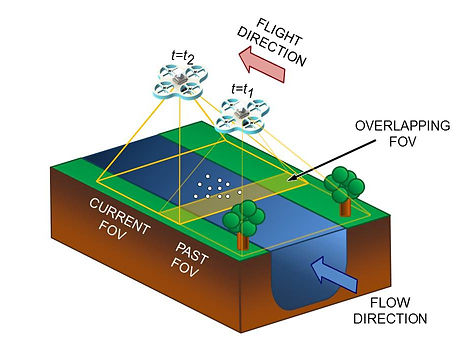

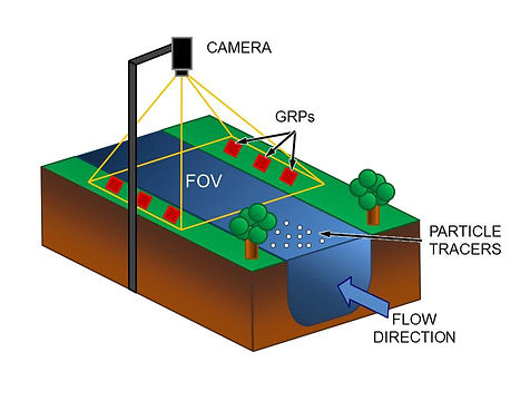
Figure 1. Comparison of current LSPIV methodology (left) and proposed methodology utilizing a UAV for image capture (right)
Figure 3. Quadcopter v1 design and components
Figure 4. Quadcopter v2 design and components
Figure 5. Detailed view of the landing gear construction for Quadcopter v2
Figure 7. Quadcopter v3 design and components
Figure 8. Detailed view of the landing gear for Quadcopter v3
Figure 9. Detailed view of the electronics assembly for Quadcopter v3
Figure 8. Example cropped image capturefrom the Quadcopter v2 with the camera gimbal and overlaid with the corresponding calculated velocity map

Figure 2. Constructed Quadcopter v1
Figure 6a-c. Quadcopter v2 in flight!