
My printer design was based upon the MendelMax 2.0 design, a model of the larger RepRap community. Reprap printers are based upon a specific type of 3D printing known as Fused Deposition Modeling (FDM). In this case, a plastic filament is heated up and extruded out of a thin nozzle as the nozzle moves in 3D space. The 3D model being printed is "sliced" into many thin layers which become 3D shapes. The nozzle is moved along this 2D path at which point the nozzle is raised to print the next layer. All of this movement is controlled by stepper motors controlled via computer software such as Sprinter. FDM is one of the simplest methods of 3D printing, but as such, has limits to resolution and can only print objects with large overhangs while using support material that has to be removed after printing.
After the first design iteration was built, the design was further improved using replacement parts that are printed using the original design. This included reinforcing the vertical supports to increase stability increasing the accuracy of the walls of the prints. The Z-carriage has also been redesigned to host two extruders. This allows for not only dual colored prints, but also multi-material prints such as dissolvable filament. Dissolvable filament is used for support material that can simply be "melted" off rather than requiring meticulous post-processing of cutting and sanding. Several examples of the most recent prints can be seen below
Alongside the purchased extruder cold end, a modified version was designed and printed to allow the 3D printer to print with flexible materials. Flexible materials are not able to be extruded with traditional cold ends because the flexibility causes the filament to get caught on the gear and kink within the cold end. Therefore, the new cold end was designed to restrict the movement of the flexible filament except for one location where the drive pulley contacts the filament to push it through the hot end. This was done with a method similar to that of the Lulzbot Flexystruder. The filament is pushed through a PTFE tube rigidly mounted within the drive motor mount. The tube's ID should be slightly larger than the diameter of the filament, about 3.18mm for 3mm filament or 2mm for 1.75mm filament. In order to account for slight variation in filament diameter, a bolt is used as a thumbscrew to press the PTFE tube closer against the hobbed pulley to increase contact with the filament and aid in feeding.
The X and Z motion of the nozzle is performed on the vertical posts. Z motion is achieved by motion in two vertical stepper motors that spin threaded rods at either size of the printer. The X carriage is coupled to these rods via corresponding nuts that are press fit into brackets on the carriage. Since the carriage is restricted to only vertical motion due to its geometry, when the threaded rod spins, the nut must compensate moving the X carriage either upward or downward. The X axis motion is controlled via a stepper motor as well except rather than moving a threaded rod the motor hosts a gear and belt that rotates about an idler gear and is mounted directly to the extruder. Therefore as the gear spins, the extruder platform moves with it. The motion is kept smooth through the use of hardened linear rods. The Y axis motion of the printer is not performed on the nozzle directly; rather the print bed itself moves. The motion is performed in the same manner as the X axis.


The newest craze in manufacturing technology is without a doubt 3D printing. While it has been around for decades, its has only recently become mainstream and within the price range for use by small businesses and the hobbyist. Many companies have sprung up developing their own printers, however I couldn't pass up the challenge to design and build my own. This would not only be satisfying but it would give me a lot of knowledge into the inner workings of the printer making it easier to troubleshoot and repair. At the same time, I could upgrade my components at any time without having to invest in a completely new printer, as would be the case in buying a off-the-shelf version. Therefore my goal for this project was to build a 3D printer to make components for future projects and repairs around my house.
3D Printer - V1
Project: 3D Printer
Timeline: 3 months (Jan. 2014 – Mar. 2014)
# of participants: 1 Person
Project Goals:
-
Design and build a custom 3D printer that is easily modifiable
-
Desired Characteristics:
-
Minimum print area of 200mm x 200mm
-
Minimal required machining
-
Limited access to tools and work area
-
Low cost compared to premade 3D printers and kits
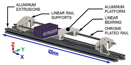
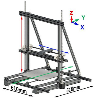

Figure 1. Assembly 3D printer v1
Figure 2. CAD model ISO view of the 3D printer v1
Figure 3. Y axis assembly
Figure 4. X axis and extruder carriage assembly
Figure 5. Y axis assembly as constructed with heated bed
Figure 6. First test print!
Figure 7a-h. Sample printed components including experimenting with dual extrusion
Reprap printers, are typically made by having someone else with a 3D printer, print out all of the components that you need. However I had no luck with finding someone with a 3D printer. Therefore my design was modified to use off-the-shelf components. The frame of the printer (see Figure 1A) uses typical aluminum extrusion, such as those available from suppliers including Adafruit Industries. The frame consists of two vertical posts mounted to a rectangular base frame. To reduce vibrations in the vertical posts, two additional extrusion beams are use as stabilizers.