The partners at Tomorrow Lab wanted to be able to prototype circuits in-house to avoid the long turn around time typical of outside, or even overseas, manufacturers. A common approach to quickly create PCB prototypes, beyond a simple bread board circuit, is to use a chemical etchant on a copper-clad board. However, this process is very time consuming as there are several steps involved, including masking the board with the circuit schematic using a photo-resistant coating or laser jet printer, and then having to consistently agitate the bath of etching while the board is submerged. Therefore, to minimize the required manpower while still achieving a fast turn around, a PCB etching machine was design. To keep costs down, it was to be built out of a re-purposed Makerbot Thing-o-matic.
Further information can be seen on Tomorrow Lab's website about this project.
PCB Milling Machine
Project: PCB Milling Machine
Timeline: 3 months (Mar. 2014 – May 2014)
# of participants: 1 Person
Project Goals:
-
Modify an underused Makerbot Thing-o-matic (3D printer) to act as a small scale CNC
-
Capable of routing PCBs for quick turnaround prototypes
-
Capable of engraving various materials
-
Route up to 2 sided PCBs
-
Sized to fit RadioShack 2-sided copper-clad boards
-
Find method to convert EagleCAD PCB files into GCode


Mechanical Design:
Two major changes were made to the Makerbot Thing-o-matic:
-
The heated bed platform was removed on the XY carriage and replaced with an adjustable 3D printed PCB holder
-
The extruder mechanism was removed from the Z carriage and replaced with a 48V DC motor
Software:
After testing several software packages, the program FlatCAM was chosen to generate the GCode. FlatCAM comes as an executable for windows and has a user-friendly UI. It accepts gerber files, exportable from EagleCAD, and converts the traces, via and pads into toolpaths which can be used to generate GCode understood by ReplicatorG. FlatCAM offers the following options:
-
Basic trace/pad isolation
-
Cleanouts of all excess copper
-
Board cutouts
-
Mirroring capabilities for double sided boards
When making a double-sided board, the orientation of the board with respect to the tool head changes when flipped to the second side. This makes it necessary to recalibrate the machine and reset the home position for the second side such that the traces are routed properly. To do this, a few lines of GCode are inserts into beginning of the file generated by FlatCAM such that it first drills a guide hole at (X,Y) = (0,0). When the board is flipped, the guide hole is used to indicate the location where the tool head should be located for the home position. Unfortunately, this method will only work if the board is rectangular and it's sides are aligned parallel to the x and y axes of the Thing-o-matic.
 |  |
|---|---|
 |  |
 |
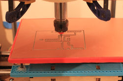
Figure 1. Modified Makerbot Thing-o-matic
Figure 2. Modifications and components needed
Figures 3a-d. Sample runs and routed PCBs from the modified Thing-o-matic
The PCB holder consists of two parts. The first (blue) is fixed directly to the XY carriage. The second (red) is connected to the first using four M3-0.5 bolts and locknuts to allow for the platform to be leveled prior to routing. The motor is mounted using a 3D printed mount that takes advantage of the mounting holes already on Z carriage to rigidly hold the motor preventing vibrations that would negatively affect a print.
A tap collet was also purchased to connect the end mill bits to the motor, ensuring the bit is centered with respect to the center of rotation of the motor.